FAQ
Dimensions
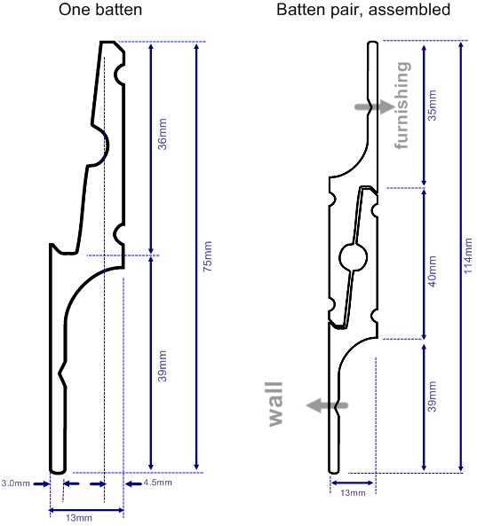
It takes two pieces of Zinterlock to make a support. One piece is simply inverted such that it fits into the other. The drawing at right indicates outer cross-sectional dimensions of the single batten, and of the assembled pair of Zinterlock battens.
Overall thickness when assembled: 13mm (this is the distance separating the item being mounted, from the mounting surface).
Overall width when assembled: 114mm.
Vertical Overlap: 37mm (this is the height one batten must be lifted over the other before it can be lowered to mate to the other). This vertical overlap will be important if the top of the object being supported is close to a ceiling.
zinterlock for sliding supports
In some cases, an object suspended on a Zinterlock batten must be slid over another surface. Horizontal sliding of one Zinterlock batten over the other may be tolerated to a limited degree depending on the weight being supported. However, Aluminium alloys are not ideally used in such sliding contact situations. If such a requirement is frequent or ongoing, a low friction high strength film can be applied to the Zinterlock mating surfaces. Please ask us for help….
Loading
Zinterlock is designed to support vertical loads only. Any horizontal component in load must be supported through other means.
Where the applied vertical load is eccentric such that it results in a moment acting to rotate or twist the Zinterlock section, then this should be supported by placing spacer supports (or additional Zinterlock supports) above or below the Zinterlock to prevent the rotation.
Zinterlock’s section has an area moment of inertia Ixx resisting bending due to vertical loads of 131.028 x 103 mm4. When combining the two battens, the combined moment of inertia Ixx of the two sections about the locking pin axis is 441.4 x 103 mm 4. Based on yield strength of 110MPA, maximum distributed (vertical) load for Zinterlock under bending is 1.7kN/m.
In practice, maximum loading for a Zinterlock mount will usually be limited by the choice and spacing of fasteners. At the design fastener location the Zinterlock extrusion is grooved to 2mm thickness. Choice and selection of fasteners should provide for shear load at this section. For example, if using 8mm fasteners then yield due to vertical shear will be at 1.8kN per fastener; this reduces to 1.3kN for 6mm fasteners or 1.1kN for 5mm fasteners.
It is therefore recommended that shear load per fastener should always be lower than 500N (equivalent to a 50kg weight) and in any case should be compliant with relevant specifications for the fastener. Add fasteners along Zinterlock’s length to distribute load.


